The fluid contained within the installation loses heat while returning to the tank, which causes thermal expansion in the tank due to emergence of heat loss. As a result, the lifespan of the tank shortens.

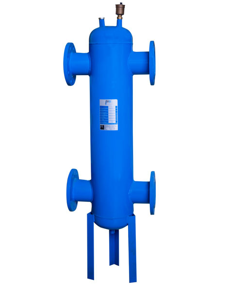
The primary purpose of the JeoTes™ Hydraulic Separator is to balance the heat by mixing the cold water coming from the installation with hot water.
There are 2 ½” clamping sleeves (thermometer or manometer) on the upper section of the hydraulic separators; as for the air release valve, there is a ½” or 1” clamping sleeve under the lower drainage based on the capacity.
- Upon demand, the hydraulic separators can be strengthened with legs.
- The products are supplied with topcoat paint and packaging.
- The products can be manufactured in desired diameters and sizes.
Based on the connection type, the nozzles can be manufactured in the following types;
- Spiral (threaded),
- Flanged,
- Straight
Body sizes of the hydraulic separators are calculated by multiplying the diameter with 3 (diameter x 3).
If you need specific diameters not shown at the table below, we can manufacture products based on your needs.